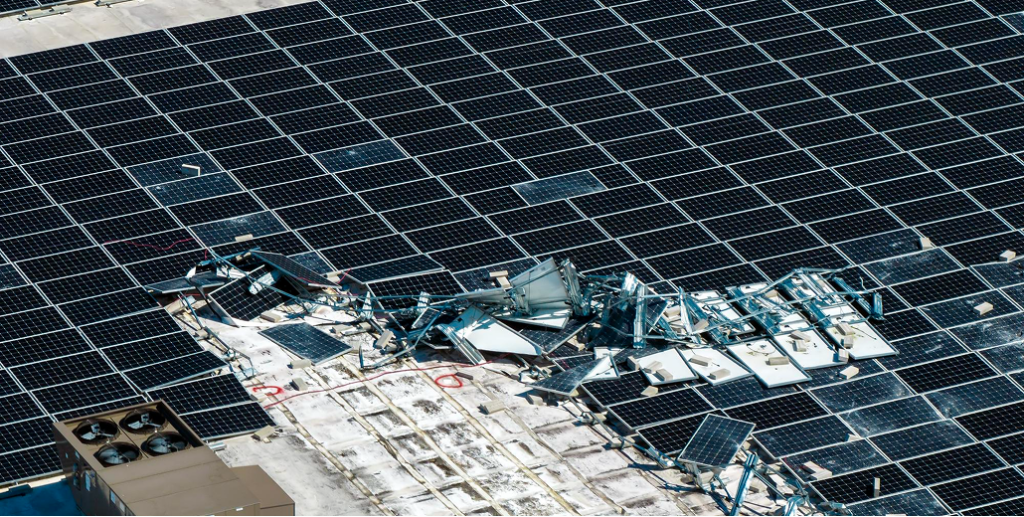
When a ground mount solar system fails in a high wind event, it almost never fails at the panel. It fails at a connection, a foundation, or a structural member that was under-specified for the site’s wind load. The panel just happens to be the part that ends up in the neighbouring field. For installers, a wind failure is the worst kind of call-back: expensive, reputation-damaging, and often uninsured if the system wasn’t certified correctly.
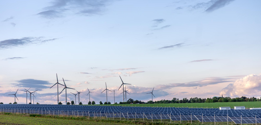
The good news is that wind failures are predictable. They happen at a small number of critical points, and every one of them can be designed against. This guide walks through exactly where ground mount systems fail under wind load, why those points fail, and how to specify and design a system that holds up across Europe’s varied wind and snow conditions, from Atlantic-exposed coasts to alpine zones.
Key takeaway
- Wind failures in ground mount systems concentrate at five critical points: the foundation, the posts, the post-to-rail connections, the rails, and the module clamps.
- Wind uplift, not downward pressure, is the force that destroys most systems. At typical tilt angles, uplift forces can be two to four times the structural dead load.
- Under-specified foundations are the most common and most catastrophic failure: posts heave out of the ground and the whole row loses its geometry.
- European wind loads are governed by Eurocode EN 1991-1-4 with a National Annex for each country, so there is no single EU wind map, and snow loading under EN 1991-1-3 adds a second structural load case that interacts with wind.
- A well-designed ground mount solar structure engineers for the load path, from the module clamp all the way down to the foundation, with no weak link.
The forces at work: why wind, not weight, is the enemy
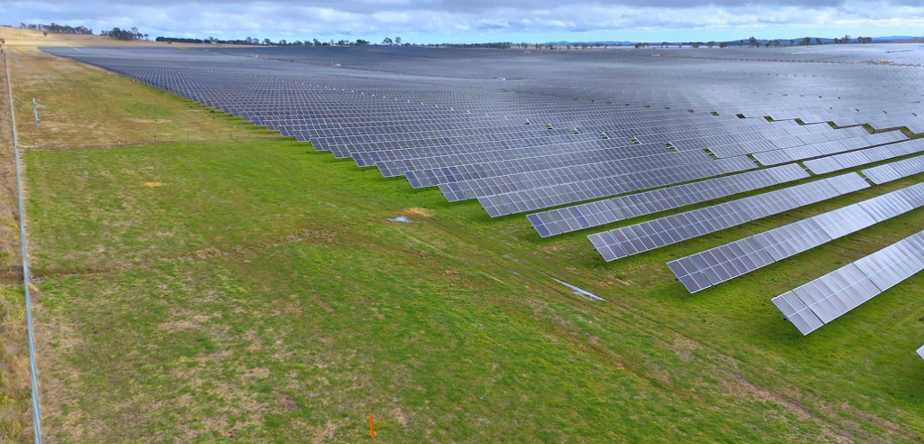
Solar arrays are effectively sails. A ground mount system holding ground mounted solar panels presents a large, flat surface to the wind, and that surface generates three distinct forces: drag (pushing the array sideways), overturning (rotating it backward or forward), and uplift (lifting it off its foundations). Of these three, uplift is the one that destroys systems.
Here’s the counterintuitive part. At the tilt angles used across most of Europe, wind uplift forces can reach two to four times the structural dead load the system was designed to carry in compression. The panels aren’t being pushed down onto their supports, they’re being pulled up and off them. A system engineered only for the weight it carries, without accounting for the uplift it experiences, is a system waiting to fail. This is why a fixed tilt ground mount has to be engineered around the worst-case wind uplift for its specific site, not just the dead load of its own components.
The five critical failure points
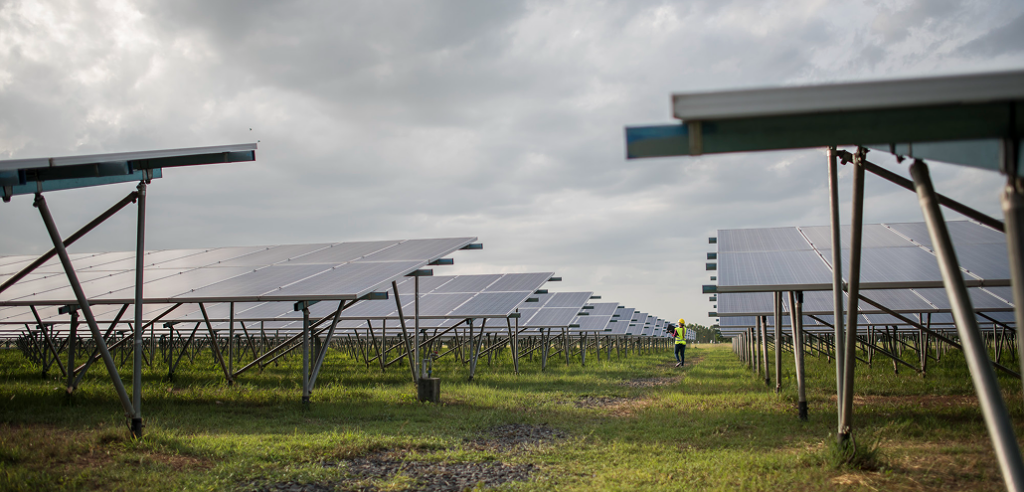
Wind failure follows the load path. The force starts at the panel surface and travels down through the structure into the ground, and it will find the weakest link along the way. Understanding the anatomy of a ground mount solar racking system helps you see where those links are. Here are the five points where systems fail, in the order the load travels.
1. The foundation (the most catastrophic failure)
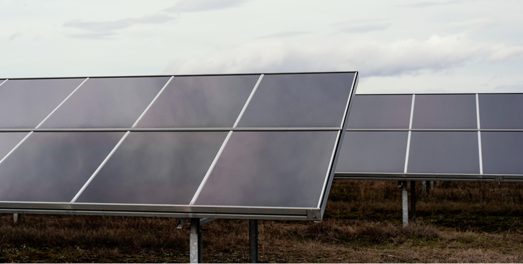
The foundation is where wind uplift is ultimately resisted, and where the most destructive failures happen. When uplift exceeds the holding capacity of the foundation, the posts literally heave out of the ground, destroying the geometry of the entire row. In sandy or saturated soils, sustained uplift can overcome the skin friction of driven piles or the dead weight of concrete ballast.
The engineering that prevents this is specific. A standard utility ground mount foundation often needs an ultimate uplift resistance of 25 to 35 kN per pile, verified on site through static pull-out testing. This is why ground mount solar foundations can’t be specified from a generic table. The right foundation type and depth depend entirely on the site’s soil, wind load, and in much of Europe its frost depth, since seasonal freezing affects how a foundation behaves. Get a geotechnical report, match the foundation to the soil, and verify the uplift resistance. Skipping this step is the single most common cause of catastrophic wind failure.
2. The posts (upright supports)
The posts carry the load from the array down to the foundation. Under wind, they experience bending as well as compression and tension, and in snow-affected regions they also carry significant additional vertical load. An under-sized post, or one made from material that corrodes and loses section over time, can buckle or snap under a load it should have handled. This is where material quality matters as much as dimensions. A post that’s structurally adequate on day one but corroding at the base will fail years earlier than its design life in coastal Atlantic, Mediterranean, or humid continental conditions.
3. The post-to-rail connections
Connections are where bending moments concentrate. Wind uplift creates bending moments at the post-to-rail connections, and a connection that relies on too few bolts, or bolts at the wrong torque, becomes a hinge point. Multi-bolt connections that loosen under repeated wind cycling are a common long-term failure mode, and freeze-thaw cycling accelerates it in colder European climates. Every connection in the load path needs to be engineered to transfer the force through, not become the point where the structure articulates and fails.
4. The rails
Rails carry the modules and span between the supports. The critical design parameter is span: rails that span too far deflect excessively under wind or snow load, which stresses the modules and can crack them. This matters more in Europe than in warmer markets, because the rail has to carry both wind uplift and, in winter, the downward weight of accumulated snow. There’s a genuine engineering tension here: greater spans reduce the number of posts and foundations (cutting cost and install time), but the rail itself has to be strong enough to carry that greater span under combined wind and snow load without excessive deflection. A rail engineered for greater spans without sacrificing stiffness is the mark of a well-designed system.
5. The module clamps
The clamp is the last link in the chain and often the weakest. If wind uplift exceeds the tensile strength of the clamp, it fractures and ejects the module from the array. A clamp that grips too little of the module frame, or is made from a material that fatigues, becomes the point where the panel separates from an otherwise intact structure. Correct clamp selection and torque is what keeps the module attached when the wind is trying hardest to remove it.
Nova’s field notes: we designed for the load path, not just the load
When we engineered the Nova Ground Mount System, we started from the failure points, not the features. The rear brace support is designed specifically to transfer wind uplift and overturning loads through the structure into the foundations, with pre-fabricated elongated holes that let the installer set the geometry precisely rather than approximating it on site. The single-bolt rail clamp isn’t just about install speed, it’s a cleaner, more repeatable connection than a multi-bolt fixing that can be torqued inconsistently.
We offer both ground screw and concrete ballast foundations because the right answer for wind uplift depends entirely on the site’s soil, and a system that only offers one foundation type forces installers to compromise on the most critical point in the whole structure. The system is snow load rated, which matters across most of Europe. The point isn’t that our system is unbreakable. It’s that we thought about where systems break and engineered those points deliberately.
European wind and snow loading: no single map
Every ground mount solar system in Europe has to be designed for its site’s wind load under Eurocode EN 1991-1-4. Unlike Australia’s single A-to-D wind region map, the Eurocode delegates the actual wind map to each country’s National Annex, so the basic wind velocity for a site in coastal Ireland, inland Germany, or the Greek islands comes from a different national document. Atlantic-facing coasts (Ireland, western UK, western France, northern Spain and Portugal) face some of the highest sustained wind loads in Europe, and mountain and ridge sites everywhere accelerate local wind speed.
Europe also adds a load case that warmer markets can largely ignore: snow. Snow loading under Eurocode EN 1991-1-3 can dominate the structural design in alpine and northern regions, with characteristic ground snow loads exceeding 4 kN/m² at altitude. Snow and wind interact in a way that catches out under-specified systems: a low-tilt array holds more snow, while a high-tilt array catches more wind. The structure has to be engineered for both, and the tilt angle chosen with both in mind. This is why generic layout drawings don’t work in Europe: the same system needs different certification for a windy Atlantic coast and a snowy alpine valley.
How to specify against wind failure
If wind failures are predictable, they’re also preventable. Five specification decisions do most of the work.

Match the foundation to the soil, not the catalogue
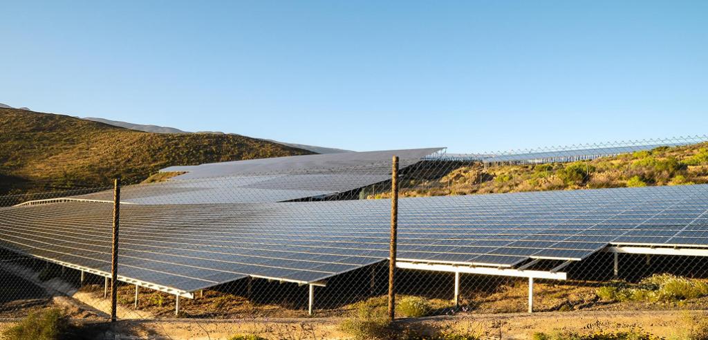
Get a geotechnical report before finalising the foundation. The report tells you what uplift resistance the soil can provide, which foundation type suits the site, and the frost depth the foundation must reach below in colder regions. A ballasted ground mount solar approach (concrete ballast resisting uplift through dead weight) suits sites where ground penetration is difficult, while ground screws generate uplift resistance by compacting and engaging the surrounding soil. The wrong choice for the soil is a failure waiting for the first big blow.
Demand National Annex-specific engineering documentation
Never accept a generic “wind resistant” claim, and never assume certification for one country transfers to another. A system certified to the German National Annex is not automatically valid for a coastal French or alpine Italian site. A racking supplier should provide engineering documentation certifying the system for your specific country’s National Annex, wind and snow load, and site conditions. For a deeper look at the structural and material specifications that matter most, see our guide to the best solar ground mount system for European conditions.
Choose materials that hold their strength for 25 years
A structural member that corrodes loses section and strength over time, which means a system that passes certification on day one can fail years later at a load it should have handled. Zinc Aluminium Magnesium (ZAM) coated steel offers significantly better corrosion resistance than standard galvanised steel, which matters most in Europe’s Atlantic and Mediterranean coastal zones and anywhere road de-icing salt is in the air.
Prioritise clean, repeatable connections
Every connection is a potential failure point, and freeze-thaw cycling in colder European climates works connections loose over time. Systems with single-bolt rail clamps and pre-fabricated holes reduce the number of connections that can be torqued incorrectly or loosen. Fewer, cleaner connections mean fewer points where the load path can break.
Respect the tilt angle, for wind and snow
Tilt angle is a balancing act in Europe. Steeper tilt angles catch more wind and generate more uplift, but they also shed snow more readily, which reduces the winter snow load on the structure. Lower tilt angles reduce wind load but hold more snow. The Nova Ground Mount System offers tilt from 10° to 30°, which lets the installer choose the angle that best balances wind load, snow shedding, and yield for the specific site rather than being locked into a single compromise.
Nova’s field notes: the cheapest racking is the most expensive mistake in a high-wind zone
We’ve seen the aftermath of wind failures on systems that were quoted to win on price. The saving on the racking was a few hundred euros per array. The cost of the failure, replacing modules, re-engineering the foundation, the insurance dispute, the reputational hit with the client, ran into tens of thousands, and in some cases the installer wore it because the original system was never certified for the site’s National Annex wind and snow loads.
On a sheltered inland site, the margin for error is generous. On an Atlantic-exposed coast, an alpine valley, or an exposed ridge anywhere, it isn’t. If you’re quoting a high-wind or high-snow site, the racking is the last place to cut cost. Specify the system that’s certified for the site’s National Annex, document it, and keep the paperwork. It’s the cheapest insurance you’ll ever buy.
The true cost of getting it wrong
A wind failure isn’t just the cost of replacement hardware. It’s the re-engineering, the re-installation, the downtime while the system isn’t generating, the insurance excess or dispute, and the damage to the installer’s reputation. For a commercial client, it can also mean a liability claim if the failure caused damage beyond the array itself. When you weigh the small upfront saving of an under-specified system against the full cost of a failure, the maths is never close. For a full breakdown of ground mount project economics, see our guide to ground mount solar cost for installers.
Build wind-resilient ground mount projects with Nova
At Nova, we’ve spent more than 15 years designing solar mounting systems that hold up in real European conditions. The Nova Ground Mount System is engineered around the load path, from the module clamp to the foundation, with a rear brace support designed to transfer wind uplift and overturning loads, single-bolt rail clamps for clean repeatable connections, and pre-fabricated holes for precise on-site geometry. It supports both ground screw and concrete ballast foundations so the foundation can be matched to the site, is snow load rated for European winters, comes in Zinc Aluminium Magnesium coated steel for corrosion resistance that lasts, and offers tilt from 10° to 30° to balance wind and snow load. It’s backed by a 25-year warranty and supported by a technical team that provides the engineering documentation your project needs.
Whether you’re quoting a sheltered inland array or an exposed Atlantic-coast or alpine project, speak to the Nova technical team for National Annex-specific engineering support, or explore the NOVA Ground Mount System specifications in detail.

Frequently asked questions
What is the most common cause of ground mount solar wind failure?
Under-specified foundations. When wind uplift exceeds the holding capacity of the foundation, the posts heave out of the ground and the whole row loses its structural geometry. This is why matching the foundation to the site’s soil, wind load, and frost depth, verified by a geotechnical report and pull-out testing, is the single most important step in preventing wind failure.
Can ballasted ground mount solar systems survive high winds?
Yes, when engineered correctly. Ballasted ground mount solar systems resist wind uplift and overturning through the dead weight of concrete ballast rather than ground penetration. They suit sites where driving piles or screws is difficult, such as rocky ground, capped landfill, or frozen ground. The key is that the ballast mass must be calculated for the site’s specific wind and snow load, an under-ballasted system can slide or overturn just as a poorly anchored one can pull out.
Do I need different certification for different European countries?
Yes. Wind and snow loads are governed by Eurocode EN 1991-1-4 and EN 1991-1-3, but each country applies its own National Annex that sets the basic wind velocity and characteristic snow load for the site. A system certified to one country’s National Annex is not automatically valid in another. Always confirm your racking supplier can provide documentation for the specific National Annex that applies to your project.
Does a lower tilt angle help in high wind?
In wind terms, generally yes: a steeper tilt presents more surface to the wind and generates more uplift, while a lower tilt reduces wind load. But in Europe there’s a trade-off, because a lower tilt holds more snow, which increases the winter structural load. The best tilt angle balances wind uplift against snow shedding for the specific site. The Nova Ground Mount System’s 10° to 30° tilt range lets installers make that balance deliberately.
How does Nova design against wind failure?
The Nova Ground Mount System is engineered around the load path. The rear brace support transfers wind uplift and overturning loads into the foundations, single-bolt rail clamps provide clean and repeatable connections, both ground screw and concrete ballast foundations are available so the foundation can be matched to the site, the system is snow load rated for European winters, ZAM-coated steel maintains structural strength over the system life, and 10° to 30° tilt lets installers balance wind and snow load per site. Nova’s technical team provides the National Annex-specific engineering documentation each project requires.